Table of Contents
Objects that might be stored in Credo and what they are
Credo can hold many different types of objects. This section explains pipe fittings and other objects that can be stored in Credo and their purpose.
Pipe/Tube

 A pipe is a tubular section or hollow cylinder, usually but not necessarily of circular cross-section, used mainly to convey substances which can flow — liquids and gases (fluids), slurries, powders, masses of small solids. It can also be used for structural applications; hollow pipe is far stiffer per unit weight than solid members.
In common usage the words pipe and tube are usually interchangeable, but in industry and engineering, the terms are uniquely defined. Depending on the applicable standard to which it is manufactured, pipe is generally specified by a nominal diameter with a constant outside diameter (OD) and a schedule that defines the thickness. Tube is most often specified by the OD and wall thickness, but may be specified by any two of OD, inside diameter (ID), and wall thickness. Pipe is generally manufactured to one of several international and national industrial standards.[1] While similar standards exist for specific industry application tubing, tube is often made to custom sizes and a broader range of diameters and tolerances. Many industrial and government standards exist for the production of pipe and tubing. The term “tube” is also commonly applied to non-cylindrical sections, i.e., square or rectangular tubing. In general, “pipe” is the more common term in most of the world, whereas “tube” is more widely used in the United States.
Both “pipe” and “tube” imply a level of rigidity and permanence, whereas a hose (or hosepipe) is usually portable and flexible. Pipe assemblies are almost always constructed with the use of fittings such as elbows, tees, and so on, while tube may be formed or bent into custom configurations. For materials that are inflexible, cannot be formed, or where construction is governed by codes or standards, tube assemblies are also constructed with the use of tube fittings.
A pipe is a tubular section or hollow cylinder, usually but not necessarily of circular cross-section, used mainly to convey substances which can flow — liquids and gases (fluids), slurries, powders, masses of small solids. It can also be used for structural applications; hollow pipe is far stiffer per unit weight than solid members.
In common usage the words pipe and tube are usually interchangeable, but in industry and engineering, the terms are uniquely defined. Depending on the applicable standard to which it is manufactured, pipe is generally specified by a nominal diameter with a constant outside diameter (OD) and a schedule that defines the thickness. Tube is most often specified by the OD and wall thickness, but may be specified by any two of OD, inside diameter (ID), and wall thickness. Pipe is generally manufactured to one of several international and national industrial standards.[1] While similar standards exist for specific industry application tubing, tube is often made to custom sizes and a broader range of diameters and tolerances. Many industrial and government standards exist for the production of pipe and tubing. The term “tube” is also commonly applied to non-cylindrical sections, i.e., square or rectangular tubing. In general, “pipe” is the more common term in most of the world, whereas “tube” is more widely used in the United States.
Both “pipe” and “tube” imply a level of rigidity and permanence, whereas a hose (or hosepipe) is usually portable and flexible. Pipe assemblies are almost always constructed with the use of fittings such as elbows, tees, and so on, while tube may be formed or bent into custom configurations. For materials that are inflexible, cannot be formed, or where construction is governed by codes or standards, tube assemblies are also constructed with the use of tube fittings.
Flange

 A flange is a plate or ring to form a rim at the end of a pipe when fastened to the pipe (for example, a closet flange). A blind flange is a plate for covering or closing the end of a pipe. A flange joint is a connection of pipes, where the connecting pieces have flanges by which the parts are bolted together. Although the word flange generally refers to the actual raised rim or lip of a fitting, many flanged plumbing fittings are themselves known as 'flanges':
Common flanges used in plumbing are the Surrey flange or Danzey flange, York flange, Sussex flange and Essex flange. Surrey and York flanges fit to the top of the hot water tank allowing all the water to be taken without disturbance to the tank. They are often used to ensure an even flow of water to showers. An Essex flange requires a hole to be drilled in the side of the tank.
There is also a Warix flange which is the same as a York flange but the shower output is on the top of the flange and the vent on the side. The York and Warix flange have female adapters so that they fit onto a male tank, whereas the Surrey flange connects to a female tank.
A flange is a plate or ring to form a rim at the end of a pipe when fastened to the pipe (for example, a closet flange). A blind flange is a plate for covering or closing the end of a pipe. A flange joint is a connection of pipes, where the connecting pieces have flanges by which the parts are bolted together. Although the word flange generally refers to the actual raised rim or lip of a fitting, many flanged plumbing fittings are themselves known as 'flanges':
Common flanges used in plumbing are the Surrey flange or Danzey flange, York flange, Sussex flange and Essex flange. Surrey and York flanges fit to the top of the hot water tank allowing all the water to be taken without disturbance to the tank. They are often used to ensure an even flow of water to showers. An Essex flange requires a hole to be drilled in the side of the tank.
There is also a Warix flange which is the same as a York flange but the shower output is on the top of the flange and the vent on the side. The York and Warix flange have female adapters so that they fit onto a male tank, whereas the Surrey flange connects to a female tank.
There are many different flange standards to be found worldwide. To allow easy functionality and inter-changeability, these are designed to have standardised dimensions. Common world standards include ASA/ANSI/ASME (USA), PN/DIN (European), BS10 (British/Australian), and JIS/KS (Japanese/Korean).
Pipe flanges are a built-in failure point on any piping system exposed to a marine atmosphere. From day one, when the flange is initially assembled, coatings on the inside hidden surfaces of the flange are damaged by the fasteners which hold the flange together. Once a flange is assembled, there is no way to paint these inner surfaces, but salt water and free oxygen intrusion, ensure that corrosion is free to occur. The result is unsightly corrosion products leaching from the flange gap and dripping onto other coated surfaces. The ultimate result could be the failure of the joint from either fastener corrosion, or gasket seal corrosion.
Elbow

 An elbow is a pipe fitting installed between two lengths of pipe or tubing to allow a change of direction, usually a 90° or 45° angle, though 22.5° elbows are also made. The ends may be machined for butt welding, threaded (usually female), or socketed, etc. When the two ends differ in size, the fitting is called a reducing elbow or reducer elbow.
Elbows are categorized based on various design features as below:
▪ Long Radius (LR) Elbows – radius is 1.5 times the pipe diameter
▪ Short Radius (SR) Elbows – radius is 1.0 times the pipe diameter
▪ 90 Degree Elbow – where change in direction required is 90°
▪ 45 Degree Elbow – where change in direction required is 45°
A 90 degree elbow is also called a “90 bend” or “90 ell”. It is a fitting which is bent in such a way to produce 90 degree change in the direction of flow in the pipe. It used to change the direction in piping and is also sometimes called a “quarter bend”. A 90 degree elbow attaches readily to plastic, copper, cast iron, steel and lead. It can also attach to rubber with stainless steel clamps. It is available in many materials like silicone, rubber compounds, galvanized steel, etc. The main application of an elbow (90 degree) is to connect hoses to valves, water pressure pumps, and deck drains. These elbows can be made from tough nylon material or NPT thread.
An elbow is a pipe fitting installed between two lengths of pipe or tubing to allow a change of direction, usually a 90° or 45° angle, though 22.5° elbows are also made. The ends may be machined for butt welding, threaded (usually female), or socketed, etc. When the two ends differ in size, the fitting is called a reducing elbow or reducer elbow.
Elbows are categorized based on various design features as below:
▪ Long Radius (LR) Elbows – radius is 1.5 times the pipe diameter
▪ Short Radius (SR) Elbows – radius is 1.0 times the pipe diameter
▪ 90 Degree Elbow – where change in direction required is 90°
▪ 45 Degree Elbow – where change in direction required is 45°
A 90 degree elbow is also called a “90 bend” or “90 ell”. It is a fitting which is bent in such a way to produce 90 degree change in the direction of flow in the pipe. It used to change the direction in piping and is also sometimes called a “quarter bend”. A 90 degree elbow attaches readily to plastic, copper, cast iron, steel and lead. It can also attach to rubber with stainless steel clamps. It is available in many materials like silicone, rubber compounds, galvanized steel, etc. The main application of an elbow (90 degree) is to connect hoses to valves, water pressure pumps, and deck drains. These elbows can be made from tough nylon material or NPT thread.
A 45 degree elbow is also called a “45 bend” or “45 ell”. It is commonly used in water supply facilities, food industrial pipeline networks, chemical industrial pipeline networks, electronic industrial pipeline networks, air conditioning facility pipeline, agriculture and garden production transporting system, pipeline network for solar energy facility, etc.
Most elbows are available in short radius or long radius variants. The short radius elbows have a center-to-end distance equal to the Nominal Pipe Size (NPS) in inches, while the long radius is 1.5 times the NPS in inches. Short elbows are widely available, and are typically used in pressurized systems. Long elbows are typically used in low-pressure gravity-fed systems and other applications where low turbulence and minimum deposition of entrained solids are of concern. They are readily available in acrylonitrile butadiene styrene (ABS plastic), polyvinyl chloride (PVC) for DWV, sewage and central vacuums, chlorinated polyvinyl chloride (CPVC) and copper for 1950s to 1960s houses with copper drains.
The image to the right shows an elbow corroded by acid.
Tee


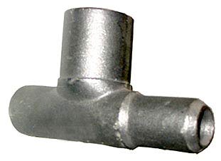
A tee is the most common pipe fitting. It is available with all female thread sockets, all solvent weld sockets, or with opposed solvent weld sockets and a side outlet with female threads. It is used to either combine or split a fluid flow. It is a type of pipe fitting which is T-shaped having two outlets, at 90° to the connection to the main line. It is a short piece of pipe with a lateral outlet. A tee is used for connecting pipes of different diameters or for changing the direction of pipe runs. They are made of various materials and available in various sizes and finishes. They are extensively used in pipeline networks to transport two-phase fluid mixtures. They are categorized as:
- Equal
- Unequal
When the size of the branch is same as header pipes, equal tee is used and when the branch size is less than that of header size, reduced tee will be used. Most common are tees with the same inlet and outlet sizes. Some of the industrial tees are Straight Tee, Reducing Tee, Double Branch Tee, Double Branch Reducing Tee, Conical Tee, Double Branch Conical Tee, Bullhead Tee, Conical Reducing Tee, Double Branch Conical Reducing Tee, Tangential Tee, and Double Branch Tangential Tee.
For more information on a reducing tee, please see the “Reducer” section.
Reducer
 A reducer is the component in a pipeline that reduces the pipe size from a larger to a smaller bore (inner diameter). The length of the reduction is usually equal to the average of the larger and smaller pipe diameters. There are two main types of reducer: concentric and eccentric reducers.
An eccentric reducer is a fitting used in piping systems between two pipes of different diameters. They are used where the diameter of the pipe on the upstream side of the fitting (i.e. where flow is coming from) is larger than the downstream side. Unlike a concentric reducer, which resembles a cone, eccentric reducers have an edge that is parallel to the connecting pipe. This results in the two pipes having offset centre lines, unlike concentric reducers. The same fitting can be used in reverse; as an eccentric increaser/expander. Horizontal liquid reducers are always eccentric, top flat, which prevents the build up of air bubbles in the system. Eccentric reducers are used at the suction side of pumps to ensure air does not accumulate in the pipe. The gradual accumulation of air in a concentric reducer would result in a large bubble that could eventually cause the pump to stall or cause cavitation when drawn into the pump. The word eccentric in regards to piping is commonly mispronounced “e-sentrik” (spelled “ecentric”). This has become an industry standard and is widely taught in schools. Horizontal gas reducers are always eccentric, bottom flat, which allows condensed water or oil to drain at low points. Reducers in vertical lines are generally concentric unless the layout dictates otherwise.
A concentric reducer, which is also known as a tapered expansion joint, is a fitting used to connect two pipes or tubes that have different inside diameters. Both tubes need to share a common centerline or alignment in order to facilitate the flow of fluid or a substance. Reducers can be manufactured using rubber, stainless steel, carbon steel, steel alloy, titanium alloy, copper, nickel, cast iron, brass, or other materials that have met the standards of the pipe industry. It is normally used in joining vertical pipes that need to be anchored for safety reasons. Concentric reducers are common in both the onshore and offshore operation of the oil and gas industry where there is a heavy volume of cargo transfer and vapor recovery.
The two ends of a concentric reducer have unequal diameters in order to achieve its purpose of joining two pipes with different diameters. Its smaller end joins with the smaller pipe while the end with the larger diameter joins with the larger pipe. The ends of a concentric reducer are put together by a cone-shaped transition section to form a single assembly. Joining of the two ends of a concentric reducer can either be done through seamless integration or through welding.
A reducer Tee is another type of pipe tee used in pipe and tube fittings. Pipe Tees are available two popular forms—have all outlets of the same size or they can be reducing tees in which they are with a combination of different outlet sizes. Reducing tee, like all pipe tees, is in the shape of T with two ends of equal size and the third one slightly smaller. In other words, reducing tee is a type of pipe fitting in which the branch port size is smaller than the ports of the run. This type of pipe fitting can also consider size reduction from one of the run ports to the other.
Shell
text…
Heat Exchanger
A heat exchanger is a piece of equipment built for efficient heat transfer from one medium to another. The media may be separated by a solid wall, so that they never mix, or they may be in direct contact. They are widely used in space heating, refrigeration, air conditioning, power plants, chemical plants, petrochemical plants, petroleum refineries, natural gas processing, and sewage treatment. The classic example of a heat exchanger is found in an internal combustion engine in which a circulating fluid known as engine coolant flows through radiator coils and air flows past the coils, which cools the coolant and heats the incoming air.
Pressure Vessel
 A pressure vessel is a closed container designed to hold gases or liquids at a pressure substantially different from the ambient pressure.
The pressure differential is dangerous and many fatal accidents have occurred in the history of pressure vessel development and operation. Consequently, pressure vessel design, manufacture, and operation are regulated by engineering authorities backed by legislation. For these reasons, the definition of a pressure vessel varies from country to country, but involves parameters such as maximum safe operating pressure and temperature.
A pressure vessel is a closed container designed to hold gases or liquids at a pressure substantially different from the ambient pressure.
The pressure differential is dangerous and many fatal accidents have occurred in the history of pressure vessel development and operation. Consequently, pressure vessel design, manufacture, and operation are regulated by engineering authorities backed by legislation. For these reasons, the definition of a pressure vessel varies from country to country, but involves parameters such as maximum safe operating pressure and temperature.
Pressure vessels can theoretically be almost any shape, but shapes made of sections of spheres, cylinders, and cones are usually employed. A common design is a cylinder with end caps called heads. Head shapes are frequently either hemispherical or dished (torispherical). More complicated shapes have historically been much harder to analyze for safe operation and are usually far more difficult to construct. Theoretically, a spherical pressure vessel has approximately twice the strength of a cylindrical pressure vessel.[1] However, a spherical shape is difficult to manufacture, and therefore more expensive, so most pressure vessels are cylindrical with 2:1 semi-elliptical heads or end caps on each end. Smaller pressure vessels are assembled from a pipe and two covers. A disadvantage of these vessels is that greater breadths are more expensive, so that for example the most economic shape of a 1,000 litres (35 cu ft), 250 bars (3,600 psi) pressure vessel might be a breadth of 914.4 millimetres (36 in) and a width of 1,701.8 millimetres (67 in) including the 2:1 semi-elliptical domed end caps.
Pressure vessels are designed to operate safely at a specific pressure and temperature, technically referred to as the “Design Pressure” and “Design Temperature”. A vessel that is inadequately designed to handle a high pressure constitutes a very significant safety hazard. Because of that, the design and certification of pressure vessels is governed by design codes such as the ASME Boiler and Pressure Vessel Code in North America, the Pressure Equipment Directive of the EU (PED), Japanese Industrial Standard (JIS), CSA B51 in Canada, Australian Standards in Australia and other international standards like Lloyd's, Germanischer Lloyd, Det Norske Veritas, Société Générale de Surveillance (SGS S.A.), Stoomwezen etc. Note that where the pressure-volume product is part of a safety standard, any incompressible liquid in the vessel can be excluded as it does not contribute to the potential energy stored in the vessel, so only the volume of the compressible part such as gas is used.
Valve

A valve is a device that regulates, directs or controls the flow of a fluid (gases, liquids, fluidized solids, or slurries) by opening, closing, or partially obstructing various passageways. Valves are technically pipe fittings, but are usually discussed as a separate category. In an open valve, fluid flows in a direction from higher pressure to lower pressure. The simplest, and very ancient, valve is simply a freely hinged flap which drops to obstruct fluid (gas or liquid) flow in one direction, but is pushed open by flow in the opposite direction.
Corrosion Circuit
text…